Timing
The LED Wheel requires precise timing to achieve persistence of vision. This section outlines the timers used by the micro-controller.
Adapting to Speed Changes
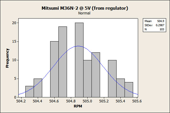
The speed of the Mitsumi DC motor ( or any DC motor ) varies slightly from rotation to rotation. The following graph is a sample of RPM readings taken from the shaft encoder. The motor is powered with 5V from a regulated power supply.

This sample indicates a slight drift of 1 RPM. This is acceptable for most applications, but for the LED Wheel ignoring these changes would create jitter in the output. To deal with these small variations in speed we must have fine control over the blinking speed.
Blinking Speed
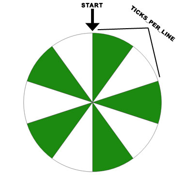
To blink a message it is convenient to visualize the LED Wheel in terms of lines. A line represents one on / off blink of the 16 LEDs. The following picture displays a simple view of one circle with 5 lines.

Next we need to know the current speed of the wheel provided by the shaft encoder. This speed can be represented in different ways: rotations per minute, rotations per second. But for a micro-controller it is useful to represent the speed as ticks per revolution.
For every LED on / LED off period of this image, we need to calculate the time in ticks it will take to display. This is calculated using the following formula.
(TICKS_PER_REVOLUTION) / (DESIRED_NUMBER_OF_LINES) = (TICKS_PER_LINE)
For example, say our TICKS_PER_REVOLUTION = 1000 and DESIRED_NUMBER_OF_LINES = 10, then our TICKS_PER_LINE would be 100.
Once we calculate the number of ticks we want for each line we must setup a timer.
Blink Phase Timer
To setup a timer in on an Atmel micro-controller we must first choose an initial frequency. The higher the frequency more exact control of time we can achieve.
TCCR1B |= _BV(WGM12) | _BV(CS11);
The previous command sets up timer 1 to run at (Fosc / 8) or 1Mhz. This also puts the timer in "clear timer on compare match" mode. This mode will clear the timer every time an output compare has occurred.
OCR1A = 1000;
The output compare value of 1000 is initially seeded to the output compare register. Every 1000 ticks @ 1Mhz this timer will fire a compare match.
TIMSK1 |= _BV(OCIE1A);
Finally the compare match interrupt vector is enabled, starting the timer.
With the timer setup we now control the exact length of each blink phase. An initial value of OCR1A = 1000; will fire every 1000 ticks @ 1MHz or once every 1 millisecond. To change the length of the blink phase we need to change the value stored in OCR1A. Example OCR1A = 978; meaning once every 0.978ms.
Synchronizing with the Shaft Encoder
To adjust the the blink phase we used the shaft encoder. The shaft encoder uses an input capture, that fires when the arm reaches the top of a rotation. To illustrate this, we place a start marker at the top of our example wheel.

Upon reaching the start marker the shaft encoder adjusts the blink phase timer with a new value for TICKS_PER_LINE. This TICKS_PER_LINE is based upon the previous rotations speed, which gives a good indication of the next rotations speed. By constantly updating the TICKS_PER_LINE every rotation the LED Wheel can display a constant image, that remains completely stationary.
Configuration Delay
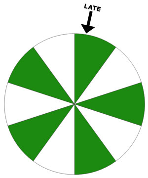
A problem arises when both the blink phase timer, and shaft encoder timer are used together to synchronize the wheel. Since we know the RPM of the wheel drifts slightly there is a possibility of missing the start signal from the shaft encoder.
This error accumulates and creates a jitter from left to right in an otherwise stationary image.

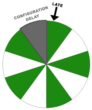
This was solved by allocating a section of the rotation dedicated to waiting for the signal from the shaft encoder.

During the configuration delay the blink timer is completely turned off. Giving the shaft encoder enough breathing room to fire its start marker at the top of the rotation.