Texas Instruments TLC5940NT LED Controller
The TLC5940NT is a LED controller chip that can power up to 16 LEDs. In this project we used three TLC5940NTs to drive 16 common anode RGB LEDs ( or 48 single color LEDs ). The TCL5940NT can set each individual LED with 4096 levels of brightness. This controller chip interfaces to the micro-controller via SPI.
Grayscale Mode
The TCL5940NT has three modes: Grayscale PWM Mode, Dot Correction Data Input Mode, and EEPROM Programming Mode. For this project we used Grayscale PWM Mode. Grayscale PWM Mode sets the brightness of the 16 connected LEDs. To program Grayscale PWM Mode we need to construct a data block.
192-bit Data Block
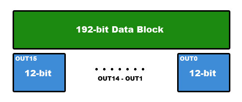
The following data block contains contains all the information needed to program the brightness of all 16 LEDs simultaneously.

In the illustration above you can see that the 192-bit block is broken up into 16 12-bit blocks. Each of these 12-bit blocks stores a number between 0 and 4095, representing the PWM power of one LED. The 16 blocks are ordered from OUT15 to OUT0.
Each block is stored MSB first ( big endian ). For example, the decimal value 1000 would be stored as 0x3E8 or 0011 1110 1000.
To send 1000 to all 16 LEDs we would send this data block:
0x3E,0x83,0xE8,0x3E,0x83,0xE8,0x3E,0x83,0xE8,0x3E,0x83,0xE8,
0x3E,0x83,0xE8,0x3E,0x83,0xE8,0x3E,0x83,0xE8,0x3E,0x83,0xE8
Sending the Data Block via SPI
Once a data block matches the above format it is ready to be sent via SPI. First we connect the TLC5940NTs SPI pins: SCLK and MOSI. SCLK is the SPI clock. MOSI ( master out slave in ) is the data out for SPI communication.
Two other non-SPI pins to connect are BLANK and XLAT. BLANK controls the power to all LEDs. XLAT is a data latch used to save a data block into the TLC5940NTs memory.
Now we can send the data block by following these steps:
- Set BLANK HIGH
- Send entire data block with SPI
- Set BLANK LOW
- Set XLAT HIGH
- Wait about 2us
- Set XLAT LOW
More details about this process can be found in the TLC5940NT data-sheet. For details on wiring see the wiring diagram.
Daisy Chaining
Hooking up more than 16 LEDs requires more than one TLC5940NT. These controllers can be easily setup to control 16+ LEDs using cascading SPI connections.
For the LED Wheel I used three TLC5940NT controllers connected to 16 RGB LEDs ( 48 independent LEDs ). The following connections are required to create a daisy chain.
- Connect a common XLAT and BLANK to all 3 chips
- Connect a common SCLK to all 3 chips
- Connect MOSI to LED controller one's SIN
- Connect SOUT of LED controller one to SIN of LED controller two
- Connect SOUT of LED controller two to SIN of LED controller three
This connection scheme is also detailed in the schematics.
Once the controller chips are daisy chained, we can now send data to configure the 48 LEDs. One TLC5940NT requires 192-bits to be transmitted via SPI. Three TLC5940NTs will require three data blocks or 576-bits.
These three data blocks can be treated as one large block and transmitted to the first LED controller in the daisy chain. These three controllers automatically divide up and assign each individual chip a 192-bit chunk of the 576-bits. Then when the XLAT is signaled all 48 LEDs are updated simultaneously.